
A combination of particles, moisture, and air lead to the eventual breakdown of hydraulic fluid. The majority of premature equipment failures are due to hydraulic fluid contamination. A structured approach to hydraulic fluid contamination control is one of the least expensive ways to extend component life and cut repeat repairs.
Understanding the ISO Cleanliness Code
In the ISO 4406 standard, fluid cleanliness is represented in a three-digit code. The first number, 18, represents the permitted particle count at 4 microns. The second number represents the particle count at 6 microns, and the last number represents the particle count at 14 microns. In general, the smaller the number the cleaner the fluid. Each step down in number represents a reduction in particle count by half.
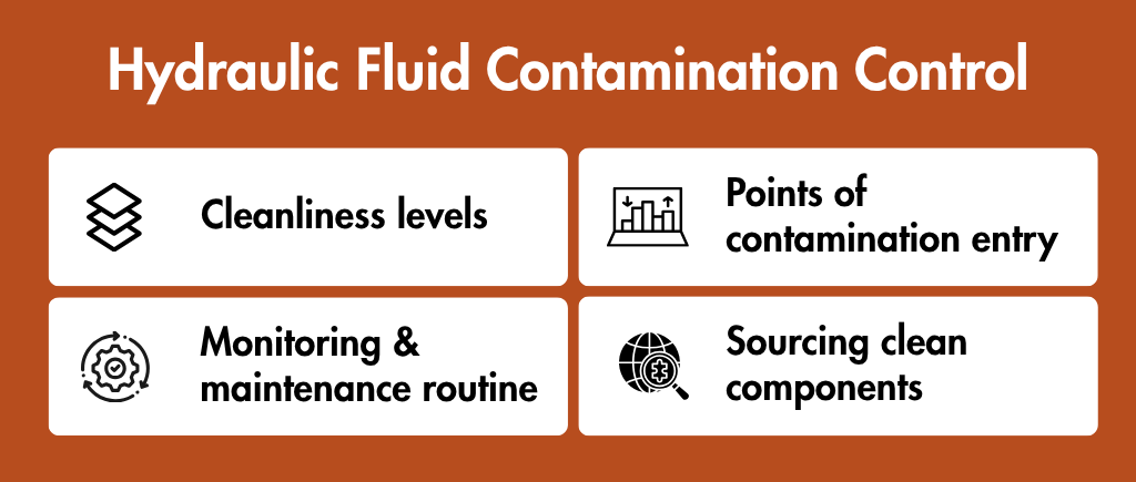
Cleanliness Levels
There is not a single target cleanliness level that can be applied to all machine components. In general, components in a circuit with higher pressure require cleaner fluid. A good starting point to establish the target hydraulic circuit cleanliness level is to use the component manufacturers recommended target cleanliness level. Documenting the plant target cleanliness level on a component ensures employees’ focus on the goal.
Points Of Contamination Entry
Oil is often introduced into a system from a drum, and if the drum contains new oil, that oil can be of very poor quality and cause system contamination. Worn rod seals and wiper seals allow contamination to enter a system. The same can be said of open reservoir covers and breather openings that draw in contaminated air. Wear debris generated within a system is also contamination. Water is especially pernicious because it causes corrosion and breaks down oil additives, thereby defeating the purpose of having a lubricating system. With a good understanding of the sources of contamination, the focus of prevention can be placed on the most important areas.
Floor Controls
There are many combined controls of prevention and filtration that can be employed. A good filler breather is a good first line of defense to keep dust and moisture out of a reservoir. New oil can be filtered prior to being added to the system. A combination of pressure and return line filters can help capture contaminants. Capped fittings, along with the use of sealed storage for hoses and fittings help prevent system contamination during maintenance.
Monitoring and Maintenance Routine
The end goal of a filtration system is only achieved if the system is monitored, and element changed when necessary. A drop in system pressure is better indication of element replacement than a time-based replacement. There are laboratory services available, either sent away or portable on-site, that can provide real time analysis of the system fluid to gauge cleanliness. Trending the data is crucial. A sudden spike in the number of particles can mean that a seal or bushing is worn.
Sourcing Clean Components
Controlling contamination is tied to components sourced. Located in Coimbatore, Teutonic Engineering, produces hydraulic cylinders and power packs, as well as other system components like filler breathers, suction strainers, and seals and adapters, and pumps. The benefit of sourcing these components from a single supplier is that the filtration and sealing components can easily be integrated into the system.
Final Thoughts
The use of clean fluids is more of a habit than an exception. Leading plants set specific goals for cleanliness levels. The entrance points to the systems are locked, results are audited, and the systems monitored. The net effect of all this is less failures of pump and valve systems, leaks in systems, and more efficient and steady operation of process machinery. This approach should be taken for a specific critical machine on the plant floor and be extended to other machines.